Optical Satellite Communication


Sout

          The European Space Agency (ESA) has programmes underway to place Satellites carrying optical terminals in GEO orbit within the next decade. The first is the ARTEMIS technology demonstration satellite which carries both microwave and SILEX (Semiconductor Laser Intro satellite Link Experiment) optical interorbit communications terminal. SILEX employs direct detection and GaAIAs diode laser technology; the optical antenna is a 25cm diameter reflecting telescope. The SILEX GEO terminal is capable of receiving data modulated on to an incoming laser beam at a bit rate of 50 Mbps and is equipped with a high power beacon for initial link acquisition together with a low divergence (and unmodulated) beam which is tracked by the communicating partner. ARTEMIS will be followed by the operational European data relay system (EDRS) which is planned to have data relay Satellites (DRS). These will also carry SILEX optical data relay terminals.

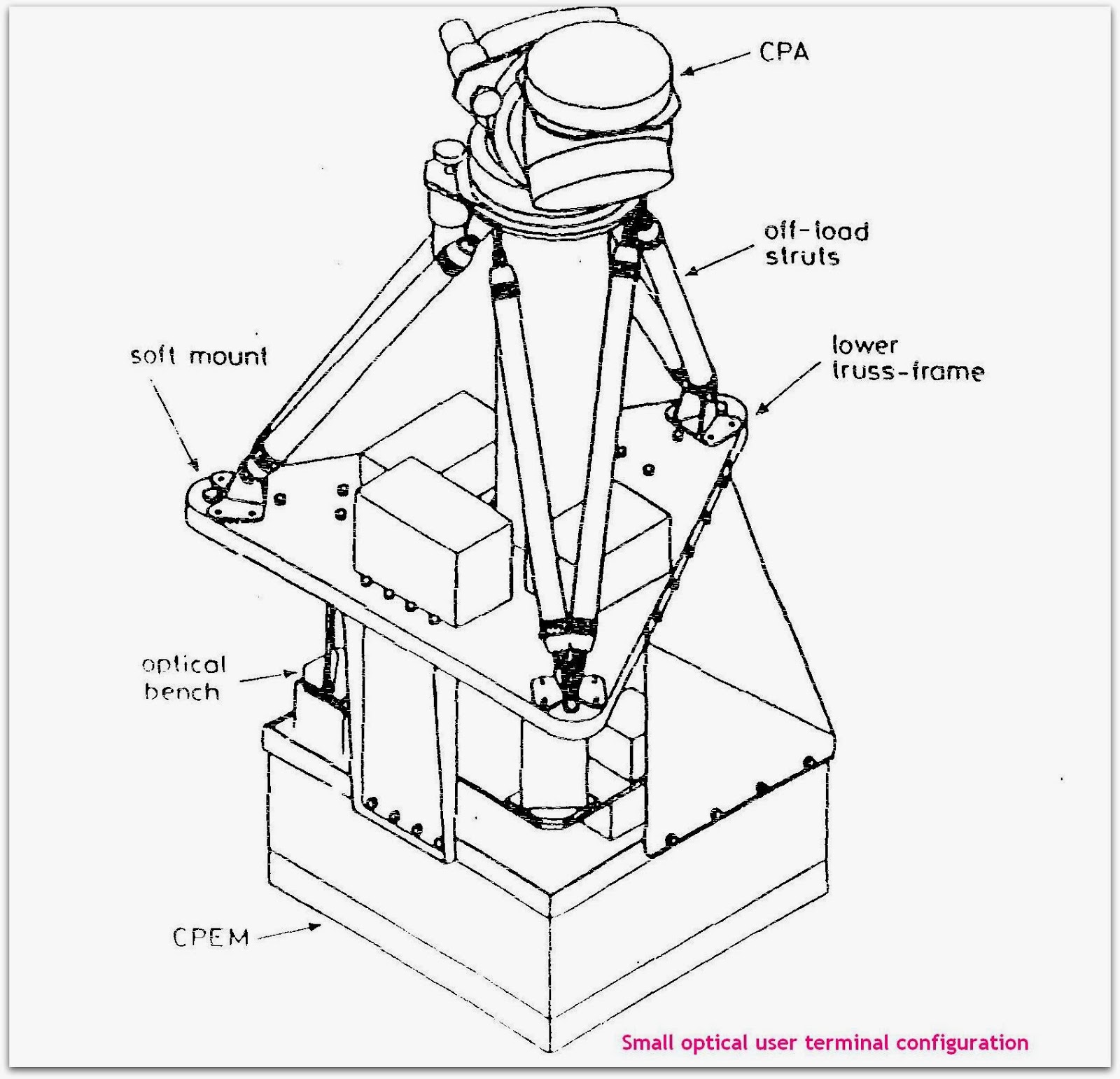
The terminal design which has been produced to meet these requirements includes a number of naval features principally, a periscopic coarse pointing mechanism (CPA) small refractive telescope, fibre coupled lasers and receivers, fibre based point ahead mechanism (PAA), anti vibration mount (soft mount) and combined acquisition and tracking sensor (ATDU). This combination has enabled a unique terminal design to be produced which is small and lightweight These features are described in the next sections.


Fine Pointing Loop

          The fine pointing loop (FPL) is required to attenuate external pointing disturbances so that the residual mispoint angle is a small fraction of the optical beam width. The closed loop tracking subsystem consists of a tracking sensor which determines the direction of the incoming communications beam with an angular resolution around 5% of the optical beam width and a fine pointing mirror assembly (FPA) which compensates beam mispointing effects. The SOUT FPL is used to compensate for frequencies upto 80 HZ.

 Optical Antenna

          The optical antenna comprises the telescope and coarse pointing assembly. The telescope is a refractive keplerian design which does not have the secondary mirror obscurration loss associated with reflective systems. The CPA uses stepping motors together with a conventional spur gear and planetary gear. The total height of the optical antenna is a major contributor to the height of the CPA above the platform which affects LEO and GEO link obscurration by solar arrays, antennas and other space craft appendages.

General optical terminal

In this system a nested pair of mechanism which perform the course pointing and fine pointing functions is used. The former is the coarse pointing assembly (CPA) and has a large angular range but a small band width while the latter, the fine pointing assembly (EPA) has a small angular range and large band width. These form elements of control loops in conjuction with acquisition and tracking sensors which detect the line of sight of the incoming optical beam. A separate point ahead mechanism associated with the transmitter sub system carries out the dual functions of point ahead and internal optical allignment.

Abstract

Satellite crosslinks generally require narrower bandwidths for increased power concentration. We can increase the power concentration by increasing  the cross link frequency with the same size antenna. But the source technology and the modulation hardware required at these higher frequency bands are still in the development stage. Use of optical frequencies will help to overcome this problem with the availability of feasible light sources and the existence of efficient optical modulation communications links with optical beams are presently being given serious considerations in intersatellite links.

Introduction

          Communication links between space crafts is an important element of space infrastructure, particularly where such links allow a major reduction in the number of earth stations needed to service the system.

Conclusion
         
          Optical intersatellite communications promises to become an important element in future space infrastructure and considerable development effort is currently underway in Europe and elsewhere. There will be a need for small optical terminals for LEO space craft once Europe’s data relay satellites are in orbit within the next five years. The small official user terminal (SOUT) programme funded by ESA seeks to fill this need for data rate around 2Mbps.


Synthetic Aperture Radar System


Processing And Storage Subsystem

          The image formation from the radar echo of the SAR instrument involves a highly sophisticated processing effort. The main function of the processing and storage subsystem is to process and store the information obtained from the SAR instrument. The processing stages involves-

v Buffering of the SAR raw data stream in real-time

v Off-line image processing and compression of the buffered SAR data

v Mass memory data management and organisation

v Reformatting and output of compressed data at downlink rate

Rationale For On-Board Processing

          Image from space under darkness or cloud cover can be obtained  by flying a synthetic aperture radar on a satellite. As the satellite  moves along its orbit ,the SAR looks out sideways from the directions of travel ,acquiring and storing the radar echoes which return from a strip of the earth's surface which is under observation.


Introduction

                   When a disaster occurs it is very important to grasp the situation as soon as possible. But it is very difficult to get the information from the ground because there are a lot of things, which prevent us from getting such important data such as clouds and volcanic eruptions. While using an optical sensor, large amount of data is shut out by such barriers. In such cases, Synthetic Aperture Radar or SAR is a very useful means to collect data even if the observation area is covered with obstacles or an observation is made at night at nighttime because SAR uses microwaves and the sensor itself radiates these. The SAR sensor can be installed in some satellite and the surface of the earth can be observed. The raw data collected by SAR are severely unfocussed and considerable processing is required to generate a focused image. The processing has traditionally been done  on ground and a downlink with a high data rate is required. This is a time consuming process as well. The high data rate of the downlink can be reduced by using a SAR instrument with on-board processing.

Processing And Storage Architecture

          The architecture of the processing and storage subsystem is shown in fig 5.   The digitised raw data enters the subsystem from the left. The data is assumed to consist of 16 bit complex samples, sampled at a rate which is higher than (20%)the chirp bandwidth. Hence it is assumed that the basebanding, demodulation and digitisation have taken place externally to this subsystem. Digital demodulation could also be performed within the subsystem. In this case, the input would consist of 8 bit real samples ,with twice the sampling rate as before. In the figure, the compressed output exits the subsystem at the right , through a number of t parallel channels.

Raw data compression with a BAQ type algorithm

          The total range of data is target dependent and very high. Compared to this the instantaneous range is considerably less. This effect is used for lossy data reduction. If this technique is used on data in a transform domain, the properties of the instrument and the SAR processor can be used to achieve even better compression ratios. This technique can be combined with the data volume reduction of the over sampled data.

X-Band Sar Instrument Demonstrator

          The X-band SAR instrument demonstrator forms the standardized part or basis for a future Synthetic Aperture Radar (SAR) instrument with active front- end. SAR is an active sensor. Active sensors carry on-board an instrument that sends a microwave pulse to the surface of the earth and register the reflections from the surface of the earth. Different sensor use different bands in the microwave regions of the electromagnetic spectrum for collecting data. In the X-band SAR instrument, the X-band is used for collecting data.

Abstract

           Synthetic Aperture Radar or SAR is an imaging radar system that  sends a microwave pulse to the surface of the earth and register  the reflections from the earth's  surface . On -board processing and compression of data obtained from the SAR is vital for image formation.

Conclusion

          Synthetic Aperture Radar is now a well established part of radar art, both  with airborne systems for surveillance and non-cooperative target identification purposes, and  with space-borne systems for geophysical remote sensing applications over the oceans, land and  polar regions. 


Welding Robots


Introduction to welding

          Welding is a process of joining different materials. The large bulk of materials that are welded are metals and their alloys although welding is also applied to the joining of other materials such as thermoplastics. Welding joins different metals or alloys with help of a number of processes in which heat is supplied either electrically or by means of a gas torch.

Abstract

          Welding being the major asset and salvation for mechanical engineering, the seminar is all about the automation of major welding processes used in industries using robots, which was hitherto done manually under hazardous and perilous working environs. The seminar dwells with two major industrial welding processes namely continuous arc welding process and spot welding process.


Why Robot Spot Welding?

          For larger works on spot welding the welding guns with cables attached is quite heavy and can easily exceed 100lb in weight. To assist the operator in manipulating the gun, the apparatus is suspended from an overhead hoist system. Even with this assistance, the spot-welding gun represents a heavy mass and is difficult to manipulate by a human worker at high rates of production desired on a car body assembly line. There are often problems with the consistency of the welded products made on such a manual line as a consequence of this difficulty.

Robotic Arc Welding System

          Robotic arc welding (RAWS) is best suited for batch production involving frequent design changes in a component and even where different components are to be handled one after the other. This is possible due to highly flexible system provided by RAWS. However the justification for installation of such a system has to be looked through return on investment by considering all the expenses (on equipment, material handling devices, training, etc.) and the likely savings on account of increased production, improved quality, savings of energy, men-hours and materials due to the reduction in reworking of components, lower turn over of employees in the shop and reduced burden of strikes, etc.       

Continuous arc welding

          Arc welding is a continuous process as opposed to spot welding which might be called a discontinuous process. Continuous arc welding is used to make long welding joints in which an air tight seal is often required between the two pieces of metals being joined. The process uses an electrode in the form of a rod or a wire of metal to supply the high electric current needed for establishing the arc. Currents are typically 100 to 300A at voltages of 10 to 30GV. The arc between the welding rod and the metal parts to be joined produces temperatures that are sufficiently high to form a pool of molten metal to fuse the two pieces together. The electrode can also be used to contribute to the molten pool, depending on the type of welding process.

Sensors

          The robotic arc welding sensor system considered here are all designed to track the welding seam and provide the information to the robot controller to help guide the welding path. The approaches used for this purposes divide into two basic categories.

v Contact sensors.

v Non-Contact sensors

Improved Product Quality

               Improved quality is in the form of more consistent welds and better repeatability in the location of welds. Even robots with relatively unimpressive repeatability specifications are able to locate the spot welds more accurately than human operators.

Introduction

          Welding technology has obtained access virtually to every branch of manufacturing; to name a few bridges, ships, rail road equipments, building constructions, boilers, pressure vessels, pipe lines, automobiles, aircrafts, launch vehicles, and nuclear power plants. Especially in India, welding technology needs constant upgrading, particularly in field of industrial and power generation boilers, high voltage generation equipment and transformers and in nuclear aero-space industry.

Conclusion

          A substantial opportunity exists in the technology of robotics to relieve people from boring, repetitive, hazardous and unpleasant work in all forms of a human labour. There is a social value as well as a commercial value in pursuing this opportunity. The commercial value of robotics is obvious. Properly applied, robots can accomplish routine, undesirable work better than humans at a lower cost. As the technology advances, and more people learn how to use robots, the robotics market will grow at a rate that will approach the growth of the computer market over the past thirty years. One might even consider robotics to be a mechanical extension of computer technology.


Storage Area Networks


Storage Components

Thus far, we have discussed devices being attached to the storage bus as though individual disks are attached. While in some very small, arbitrated loop configurations, this is possible, it is highly unlikely that this configuration will persist. More likely, storage devices such as disk and tape are attached to the storage fabric using a storage controller such as an EMC Symmetrix or a Compaq StorageWorks RAID controller. IBM would refer to these types of components as Fibre RAID controllers.


Highly Available Solutions

One of the benefits of storage area networks is that the storage can be managed as a centralized pool of resources that can be allocated and re-allocated as required. This powerful paradigm is changing the way data centers and enterprises are built, however, one of the biggest issues to overcome is that of guaranteed availability of data. With all of the data detached from the servers, the infrastructure must be architected to provide highly available access so that the loss of one or more components in the storage fabric does not lead to the servers being unable to access the application data. All areas must be considered including.

Introduction

SANs evolved to address the increasingly difficult job of managing storage at a time when the storage usage is growing explosively. With devices locally attached to a given server or in the server enclosure itself, performing day-to-day management tasks becomes extremely complex; backing up the data in the datacenter requires complex procedures as the data is distributed amongst the nodes and is accessible only through the server it is attached to.  As a given server outgrows its current storage pool, storage specific to that server has to be acquired and attached, even if there are other servers with plenty of storage space available. Other benefits can be gained such as multiple servers can share data (sequentially or in some cases in parallel), backing up devices can be done by transferring data directly from device to device without first transferring it to a backup server.

Fibre Channel Switched Fabric

In a switched fibre channel fabric, devices are connected in a many-to-many topology using fibre channel switches, as shown in Figure 4 below. When a host or device communicates with another host or device, the source and target setup a point-to-point connection (just like a virtual circuit) between them and communicate directly with each other. The fabric itself routes data from the source to the target. In a fibre channel switched fabric, the media is not shared. Any device can communicate with any other device (assuming it is not busy) and communication occurs at full bus speed (1Gbit/Sec or 2Gbit/sec today depending on technology) irrespective of other devices and hosts communicating.

Hubs

Hubs are the simplest form of fibre channel devices and are used to connect devices and hosts into arbitrated loop configurations. Hubs typically have 4, 8, 12 or 16 ports allowing up to 16 devices and hosts to be attached, however, the bandwidth on a hub is shared by all devices on the hub. In addition, hubs are typically half-duplex (newer full duplex hubs are becoming available). In other words, communication between devices or hosts on a hub can only occur in one direction at a time. Because of these performance constraints, hubs are typically used in small and/or low bandwidth configurations.

Bridges and Routers

In an ideal world, all devices and hosts would be SAN-aware and all would interoperate in a single, ubiquitous environment. Unfortunately, many hosts and storage components are already deployed using different interconnect technologies. To allow these types of devices to play in a storage fabric environment, a wide variety of bridge or router devices allow technologies to interoperate. For example, SCSI-to-fibre bridges or routers allow parallel SCSI (typically SCSI-2 and SCSI-3 devices) to be connected to a fibre network, as shown in Figure 8 below. In the future, bridges will allow iSCSI (iSCSI is a device interconnect using IP as the communications mechanism and layering the SCSI protocol on top of IP) devices to connect into a switch SAN fabric.

SAN Backup

Storage area networks provide many opportunities to offload work from the application hosts. Many of the devices in the SAN (either hosts or storage controllers) have CPUs and memory and are capable of executing complex code paths. In addition, any device can communicate with any other device, the SAN provides a peer-to-peer communication mechanism. This leads to such things as SAN-based backups. A storage controller can easily initiate the backup of a disk device to a tape device on the SAN without host intervention. In some cases, hybrid backup solutions are implemented where file system related information is provide by the host, but bulk copying of the data blocks is done directly from storage controller to tape device.

Conclusion


Storage area networks provide a broad range of advantages over locally connected devices. They allow computer units to be detached from storage units, thereby providing flexible deployment and re-purposing of servers and storage to suit current business needs. You do not have to be concerned about buying the right devices for a given server, or with re-cabling a datacenter to attach storage to a specific server.

Nanotechnology


An Overview

          Nanotechnology is the manipulation of matter on the nanoscale. A nanometer is a very small measure of length-it is one billionth of a meter, a length so small that only three or four atoms lined up in a row would be a nanometer. So, nanotechnology involves designing and building materials and devices where the basic structure of the material or device is specified on the scale of one or a few nanometers. Ultimately, nanotechnology will mean materials and devices in which every atom is assigned a place, and having every atom in the right place will be essential for the functioning of the device. Nanotechnology cannot be defined as a definite branch of science but different from the conventional ones that we have as of now. It is set to encompass all the technological aspects that we have today and is nothing but the extension of scientific applications to a microscopic scale and thereby reaching closer to perfection if not right there.

Nanomachines: An Insight

          Nanomachines are machines of dimensions in the range of nanometers. They include micro scale replicas of present day machines like the nanogears,nanoarms or the nanorobots as well as futuristic machines which have no present day analogs, like the assembler which can assemble atoms to produce further machines or assembler themselves.


Carbon Nanotubes

          In 1991, a Japanese scientist Sumio Iijima used a high-resolution transmission electron microscope to study the soot created in an electrical discharge between two carbon electrodes at the NEC Fundamental Research Laboratory in Tsukuba, Japan. He found that the soot contained structures that consisted of several concentric tubes of carbon, nested inside each like Russian dolls. These were termed as ‘Carbon Nanotubes’.

          Later efficient ways of making large quantities of these multiwall nanotubes were developed. Subsequently, 1993, single-wall nanotubes were tens of nanometers across, the typical diameter of a single-wall nanotube was just one or two nanometers. The past decade has seen an explosion of research into both types of nanotube.

Hurdles And Challenges

          An important challenge to overcome is one of engineering. How can we physically build machines out of atoms? Rearranging atoms into new shapes is essentially building new molecules and this is no easy task. Using contemporary technology to rearrange atoms has been said to be analogous to assembling LEGO blocks while wearing boxing gloves. It is virtually impossible to snap individual atoms together. All we can do is crudely push large piles of them together and hope for the best. Scientists hope that once this initial challenge is overcome, nanomachines will usher in a new age of molecular engineering and previous problems will be a thing of the past. The new machine will allow scientists to take off the boxing gloves and accurately snap together individual atoms to build virtually any molecule.

In order to make new molecules, a nanomachine has to somehow ‘grab individual atoms with its pincers and move them into new positions or attach them to other molecules.  There are serious problems that need to be overcome. Consider, for example, the fact that a nanomachine’s pincers will be made out of several atoms and will therefore be larger than the individual atoms that it needs to move around. This means that the intricacy and accuracy of the nanomachines movement will be severely limited. It will be clumsy. Assembling atoms would be like trying to piece together a mechanical wristwatch with your fingers rather than small tweezers.

Synthesis Of Nanomachines

The present generation micromachines which fall in the category of nanomachnes in the sense that they are made by molecular technology are currently synthesized by means of chemical reactions. As of now, chemical synthesis is conducted almost exclusively in solution, where reagent molecules move by diffusion and encounter one another in random positions and orientations.

Conclusion

          All the applications mentioned in this paper exhibit a wealth of properties and phenomena. While many of these are understood, others remain controversial, and all these fields are sure to remain an exciting area of science for years to come. The amazing predictions discussed are not in doubt. Like any new technology, however many of these have to outperform current technologies to gain a foothold. All these challenges will keep researchers busy for a long time to come. 


Poly Fuse


The Basics

          Technically Polyfuses are not fuses but Polymeric Positive Temperature Coefficient Thermistors. For thermistors characterized as positive temperature coefficient, the device resistance increases with temperature. The PPTC circuit protection devices are formed from thin sheets of conductive semi-crystalline plastic polymers with electrodes attached to either side. The conductive plastic is basically a non-conductive crystalline polymer loaded with a highly conductive carbon to make it conductive. The electrodes ensure the distribution of power through the circuit.

Surface Mount Resettable Fuses

          This surface mount polyfuse family of polymer of polymer based resettable fuses provides reliable over current protection for a wide range of products such as computer motherboards, USB hubs and ports, CD/DVD drives , digital cameras and battery packs. Each of these polyfuse series features low voltage drops and fast trip times while offering full resettability. This makes each an ideal choice for protection in datacom and battery powered applications where momentary surges may occur during interchange of batteries or plug and play operations.


Abstract

          A fuse is a one time over current protection device employing fusible link that melts after the current exceeds a certain level for a certain length of time. Typically, a wire or chemical compound breaks the circuit when the current exceeds the rated value.                          

EDGES OVER CONVENTIONAL FUSES

v Over current protection

v Low base resistance

v Latching operation

v Automatic resettability

v Short time to trip

Principle Of Operation

          PPTC circuit protection devices are formed from a composite of semi-crystalline polymer and conductive carbon particles. At normal temperature the carbon chains form low resistance conductive network through the polymer. In case an excessive current flows through the device, the temperature of the conductive plastic material rises. When the temperature exceeds the device’s switching temperature, the crystallides in the polymer suddenly melts and become amorphous. The increase in volume during melting of the crystalline phase cause separation of the conductive particles and results in a large non-linear increase in the resistance of the device. The resistance typically increases by 3 or orders of magnitude.

Battery Strap Resettable Fuses

          This type profile strap type polyfuse family of resettable fuses provides thermal and over charge protection for rechargeable battery packs commonly used in portable electronics such as mobile phones, notebook computers and camcorders.

Applications for Resettable Circuit Protection in Automotive Electronics

          The conventional solution groups similar circuits together and protects them all with a single fuse. The fuse must be sized to carry the sum of the currents drawn by each of the protected loads; and, to limit risk of damage and fire, the wires feeding from the fuse to each load must be chosen according to the fuse size selected. This design practice often results in oversized wires with high current-carrying capability feeding loads that require relatively low currents. Using heavy-gauge wire also requires use of larger terminals and connectors, which further increases cost, size, and weight. It also increases harness weight, and the weight of the automobile, which has an effect on fuel efficiency.

Introduction

          Polyfuses is a new standard for circuit protection .It is re-settable by itself. Many manufactures also call it as Polyswitch or Multifuse. Polyfuses are not fuses but Polymeric Positive temperature Coefficient Thermistors (PPTC). We can use several circuit protection schemes in power supplies to provide protection against fault condition and the resultant over current and over temperature damage.  

Conclusion


          Polymeric Positive Temperature Coefficient device provide net cost savings through reduced component count and reduction in wire size. They can help provide protection against short circuits in wire traces and electronic components. The low resistance, relatively fast time to trip and low profile of these devices improve reliability.

Virtual Retinal Display


Virtual Retinal Display- A system overview

The VRD can be considered a portable system that creates the perception of an image by scanning a beam of light directly into the eye. Most displays directly address a real image plane (typically a CRT or matrix-addressed LCD) which might be relayed to form a larger, more distant image for a head-mounted display (HMD). The VRD uses a scanned, modulated light beam to treat the retina as a projection screen, much as a laser light show would use the ceiling of a planetarium. The closest previously existing device would be the scanning laser opthalmoscope (SLO) which scans the retina to examine it; the SLO is designed to capture light returning from the eye whereas the VRD is designed as a portable display.

Stereographic Displays using VRD

          As discussed previously while treating the possibility of three-dimensional imaging systems using VRD there are two cues by which the human beings perceive the real world namely the accommodation cue and the stereo cue. There is a mismatch of the information conveyed by the two cues in projection systems so that prolonged viewing can lead to some sort of psychological disorientation.


A True Stereoscopic Display

The traditional head-mounted display used for creating three dimensional views projects different images into each of the viewer's eyes. Each image is created from a slightly different view point creating a stereo pair. This method allows one important depth cue to be used, but also creates a conflict. The human uses many different cues to perceive depth. In addition to stereo vision, accommodation is an important element in judging depth. Accommodation refers to the distance at which the eye is focused to see a clear image. The virtual imaging optics used in current head-mounted displays place the image at a comfortable, and fixed, focal distance.

Laser safety analysis

          Maximum Permissible Exposures (MPE) have been calculated for the VRD in both normal viewing and possible failure modes. The MPE power levels are compared to the measured power that enters the eye while viewing images with the VRD. The power levels indicate that the VRD is safe in normal operating mode and failure modes.

Pupil Expander 

Nominally the entire image would be contained in an area of 2 mm2. The exit-pupil expander is an optical device that increases the natural output angle of the image and enlarges it up to 18 mm on a side for ease of viewing. The raster image created by the horizontal and vertical scanners passes through the pupil expander and on to the viewer optics. For applications in which the scanned-beam display is to be worn on the head or held closely to the eye, we need to deliver the light beam into what is basically a moving target: the human eye. Constantly darting around in its socket, the eye has a range of motion that covers some 10 to 15 mm. One way to hit this target is to focus the scanned beam onto exit pupil expander. When light from the expander is collected by a lens, and guided by a mirror and a see-through monocle to the eye, it covers the entire area over which the pupil may roam.

Abstract

The Virtual Retinal Display (VRD) is a personal display device under development at the University of Washington's Human Interface Technology Laboratory in Seattle, Washington USA. The VRD scans light directly onto the viewer's retina. The viewer perceives a wide field of view image. Because the VRD scans light directly on the retina, the VRD is not a screen based technology. The VRD was invented at the University of Washington in the Human Interface Technology Lab (HIT) in 1991. The development began in November 1993. The aim was to produce a full color, wide field-of-view, high resolution, high brightness, low cost virtual display. Microvision Inc. has the exclusive license to commercialize the VRD technology. This technology has many potential applications, from head-mounted displays (HMDs) for military/aerospace applications to medical society.

Manufacturing

The same characteristics that make the VRD suitable for medical applications, high luminance and high resolution, make it also very suitable for a manufacturing environment. In similar fashion to a surgery, a factory worker can use a high luminance display, in conjunction with head tracking, to obtain visual information on part or placement locations. Drawings and blueprints could also be more easily brought to a factory floor if done electronically to a Virtual Retinal Display (with the option of see-through mode). Operator interface terminals on factory floors relay information about machines and processes to workers and engineers. Thermocouple temperatures, alarms, and valve positions are just a few examples of the kind of information displayed on operator interface terminals. Eyeglass type see-through Virtual Retinal Displays could replace operator interface terminals. A high luminance eyeglass display would make the factory workers and engineers more mobile on the factory floor as they could be independent of the interface terminal location.

Conclusion

Various strategic agencies have already started working with the VRD and with so much at stake, status reports on progress are not readily available. Nevertheless we can say that right now, all those engineers, fighter pilots and partially sighted people working with VRD will be struggling with different facets of the same problem. 


Holographic Versatile Disc


Holography

A hologram is a block or sheet of photosensitive material which records the interference of two light sources.  To create a hologram, laser  light  is  first  split  into  two  beams,  a  source  beam  and  a reference beam.  The source beam is then manipulated and sent into the photosensitive material.    Once  inside  this  material,  it intersects the reference beam and the resulting interference of laser light  is  recorded  on  the  photosensitive  material,  resulting  in  a hologram.   Once a hologram is recorded, it can be viewed with only the reference beam.  The reference beam is projected into the hologram at the exact angle it was projected during recording.  When  this  light  hits  the  recorded  diffraction  pattern,  the  source beam  is regenerated out of the refracted light.  An exact copy of the  source  beam  is  sent  out  of  the hologram  and can  be  read by optical  sensors.    For  example,  a  hologram  that  can  be  obtained from  a  toy  store  illustrates  this  idea.    Precise laser equipment is used at the factory to create the hologram.  A recording material which can recreate recorded images out of natural light is used so the  consumer  does  not  need  high-tech  equipment  to  view  the information  stored  in  the  hologram.    Natural light becomes the reference beam and human eyes become the optical sensors. 


Abstract

Currently data access times are extremely slow for magnetic disks when compared to the speed of execution of CPUs so that any improvement in data access speeds will greatly increase the capabilities of computers, especially with large data and multimedia files. Holographic memory is a technology that uses a three dimensional medium to store data and it can access such data a page at a time instead of sequentially, which leads to increases in storage density and access speed. Holographic data storage systems are very close to becoming economically feasible. Obstacles that limit holographic memory are hologram decay over time and with repeated accesses, slow recording rates, and data transfer rates that need to be increased. Photorefractive crystals and photopolymers have been used successfully in experimental holographic data storage systems.

Page-Level Parity Bits

Once error-free data is recorded into a hologram, methods which read data back out of it need to be error free as well.  Data in page format requires a new way to provide error control.  Current error control methods concentrate on a stream of bits.    Because  page data  is  in  the  form  of  a  two  dimensional  array,  error  correction needs  to  take  into  account  the  extra  dimension  of  bits.    When  a page  of  data  is  written  to  the  holographic  media,  the  page  is separated into smaller two dimensional arrays.  These sub sections are appended with an additional row and column of bits.    The added bits calculate the parity of each row and column of data.  An odd number of bits in a row or column create a parity bit of 1 and an even number of bits create a 0.   A parity bit where the row and column meet is also created which is called an overall parity bit.    The sub sections are rejoined and sent to the holographic medium for recording.

Holographic Versatile Disc (HVD)

Holographic recording technology records data on discs in the form of laser interference fringes, enabling discs the same size as today's DVDs to store more than one terabyte of data (200 times the capacity of a single layer DVD), with a transfer rate of over one gigabit per second (40 times the speed of DVD). This approach is rapidly gaining attention as a high-capacity, high-speed data storage technology for the age of broadband.

Introduction

Devices that use light to store and read data have been the backbone of data storage for nearly two decades. Compact discs revolutionized data storage in the early 1980s, allowing multi-megabytes of data to be stored on a disc that has a diameter of a mere 12 centimeters and a thickness of about 1.2 millimeters. In 1997, an improved version of the CD, called a digital versatile disc (DVD), was released, which enabled the storage of full-length movies on a single disc.

Challenges

During the retrieval of data the reference beam has to be focused at exactly the same angle at which it was projected during recording. A slight error can cause a wrong data page to be accessed.  It is difficult to obtain that much of accuracy. The crystal used as the photographic filament must have exact optical characteristics such as high diffraction efficiency, storage of data safely without any erasure and fast erasure on application of external stimulus light ultra violet rays.  With the repeated number of accesses the holograms will tend to decay. 

Conclusion


The future of holographic memory is very promising. The page access  of  data  that  holographic memory creates will provide a window  into  next  generation  computing  by  adding  another dimension  to  stored  data.    Finding holograms in personal computers might be a bit longer off, however.  The large cost of high-tech optical equipment would make small-scale systems implemented with holographic memory impractical.