Night Vision Technology


 Atoms

Atoms are constantly in motion. They continuously vibrate, move and rotate. Even the atoms that make up the chairs that we sit in are moving around. Solids are actually in motion! Atoms can be in different states of excitation. In other words, they can have different energies. If we apply a lot of energy to an atom, it can leave what is called the ground-state energy level and move to an excited level. The level of excitation depends on the amount of energy applied to the atom via heat, light or electricity.

Types Of Thermal Imaging Devices

Most thermal-imaging devices scan at a rate of 30 times per second. They can sense temperatures ranging from -4 degrees Fahrenheit (-20 degrees Celsius) to 3,600 F (2,000 C), and can normally detect changes in temperature of about 0.4 F (0.2 C).


 Introduction

Night vision is a spy or action movie you've seen, in which someone straps on a pair of night-vision goggles to find someone else in a dark building on a moonless night.  With the proper night-vision equipment, you can see a person standing over 200 yards (183 m) away on a moonless, cloudy night. Night vision can work in two very different ways, depending on the technology used.
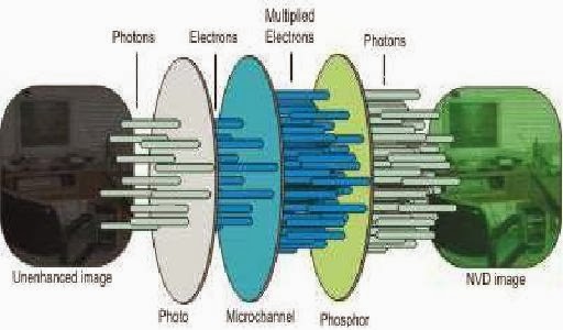
Image Enhancement

                    Image enhancement technique is used in night vision technology. In fact, image-enhancement systems are normally called night-vision devices (NVDs). NVDs rely on a special tube, called an image-intensifier tube, to collect and amplify infrared and visible light.

ABSTRACT

        Night vision is used to locate an object which is 200 yards away even in moonless, cloudy night. Night vision can work into two different ways, depending on the  technology used .They are image enhancement and thermal imaging. Image enhancement works by collecting lower portion of infrared light spectrum. Thermal imaging operates by capturing the upper portion of the infrared light spectrum .

Enhanced Spectral Range

Enhanced spectral range techniques make the viewer sensitive to types of light that would be invisible to a human observer. Human vision is confined to a small portion of the electromagnetic spectrum called visible light. Enhanced spectral range allows the viewer to take advantage of non-visible sources of electromagnetic radiation (such as near-infrared or UV radiation).

Performance Attributes

There are three important attributes for judging performance. They are: sensitivity, signal and resolution. As the customer, you need to know about these three characteristics to determine the performance level of a night vision system.

Sensitivity, or photo response, is the image tube's ability to detect available light. It is usually measured in "uA/lm," or microamperes per lumen. ITT's advanced technology and processing enable us to give our customers products with outstanding sensitivity.

Conclusion 

Night vision is used to locate an object which is 200 yards away even in moonless , cloudy night .The original purpose of night vision was to locate enemy targets at night.


Plasma Display


What is Plasma?

The central element in a fluorescent light is a plasma, a gas made up of free-flowing ions (electrically charged atoms) and electrons (negatively charged particles). Under normal conditions, a gas is mainly made up of uncharged particles. That is, the individual gas atoms include equal numbers of protons (positively charged particles in the atom's nucleus) and electrons. The negatively charged electrons perfectly balance the positively charged protons, so the atom has a net charge of zero.

Inside the Display

The xenon and neon gas in a plasma television is contained in hundreds of thousands of tiny cells positioned between two plates of glass. Long electrodes are also sandwiched between the glass plates, on both sides of the cells. The address electrodes sit behind the cells, along the rear glass plate. The transparent display electrodes, which are surrounded by an insulating dielectric material and covered by a magnesium oxide protective layer, are mounted above the cell, along the front glass plate.


Contrast ratio

Contrast ratio is the difference between the brightest and darkest parts of an image, measured in discrete steps, at any given moment. Generally, the higher the contrast ratio, the more realistic the image is. Contrast ratios for plasma displays are often advertised as high as 10,000:1. On the surface, this is a significant advantage of plasma over other display technologies. Yet there are no standardized tests for contrast ratio, meaning that each manufacturer can publish virtually any number. However, most manufactures follow an ANSI standard or do full on full off test. ANSI uses a checkered test pattern and measure the darkest blacks and the lightest whites at the same time, this gives a more accurate, real world rating.

Plasma TV  

Plasma television is a flat, lightweight surface covered with millions of tiny glass bubbles. Each bubble contains a gas-like substance, the plasma, and has a phosphor coating. Think of the bubbles as the pixels. Essentially millions of Neon signs.

Uniform screen brightness

Unlike some rear and front projection televisions that suffer from uneven screen brightness -- seen as "hot spots" in the middle of the screen or a darkening near the edges and especially corners -- plasma displays illuminate all pixels evenly across the screen.

 Abstract

A plasma display is made up of many thousands of gas-filled cells that are sandwiched in between two glass plates, two sets of electrodes, dielectric material, and protective layers.  The address electrodes are arranged vertically between the rear glass plate and a protective layer.  This structure sits behind the cells in the rear of the display, with the protective layer in direct contact with the cells.  On the front side of the display there are horizontal display electrodes that sit in between a magnesium-oxide (MgO) protective layer and an insulating dielectric layer. 

Conclusion


Plasma screens first entered the US market towards the end of 1999, but the concept has been around since its inception in July of 1964 at the University of Illinois. The first displays were nothing more than points of light created in laboratory experiments. The technology was developed and improved, and by the late 60's, it had become advanced enough to allow the scientists to construct geometric shapes. Today the progression in high speed digital processing, materials, and advanced manufacturing technology has made full color, bright plasma displays possible.


Heliodisplay


Working of Heliodisplay

The Heliodisplay transforms water into a unique screen of fine vapour, suspended in mid-air to create a nearly invisible screen into which any image can be projected. The display can create a true 3D hologram effect when the right content is used. Heliodisplay images are not holographic although they are free-space, employing a rear projection system in which images are captured onto a nearly invisible plane of transformed air.

Introduction

In late 2003, a small company from the San Francisco Bay Area demonstrated a unique revolutionary display technology. The (then) prototype device projected an image in thin air just above it, creating an illusion of a floating hologram, reminiscent of the famous scene from 'Star Wars' in which R2-D2 projects a hologram of Princess Leia.

Displaying an image using conventional projectors requires a non-transparent medium, typically screens, walls, or even water, but air, which is transparent, cannot be used. A more recent development is the FogScreen, which creates an image in midair by employing a large, non-turbulent airflow to protect the dry fog generated within from turbulence. The result is a thin, stable sheet of fog, sandwiched between two layers of air, on which an image can be projected and even walked through.


Volumetric displays

While head-worn displays attempt to create the appearance of virtual objects within some work space, volumetric dis¬plays actually create the 3D image of a surface within a volume. The surface can be viewed from arbitrary viewpoints with proper eye accommodation since each point of light has a real origin in 3D. Tracking of the viewer is not necessary.

Abstract

The Heliodisplay is a free-space display developed by IO2 technologies. A projector is focused onto a layer of mist in mid-air, resulting in a two-dimensional display that appears to float. This is similar in principle to the cinematic technique of rear projection. As dark areas of the image may appear invisible, the image may be more realistic than on a projection screen, although it is still not volumetric. Looking directly at the display, one would also be looking into the projector's light source.

Dual-sided projection

To accentuate the sensation that these virtual objects actually exist in the physical world, the dual-sided capabilities of the FogScreen are used to show both the front and back of the objects, so that viewing the scene from opposite sides will present a consistent perception.

Virtual Forest

Virtual Forest was modified to be used with the FogScreen to show how a first person style interfaces would feel, and to show off some advanced real-time rendering techniques on the novel display. A user can navigate the forest by using a tracked wireless joystick to control their velocity and direction. Different buttons also allow the user to look around and change the direction of the sunlight.

Applications

Proposed applications for the real-world Heliodisplay include:

• Advertising and Promotion, e.g.: trade shows; in-store displays; museum, movie and casino displays; theme parks.

Conclusion


Since 2003, IO2 Technology, the California-based company Dyner founded to commercialize his invention, began selling his device under the brand name Heliodisplay M2 for just under $20,000, out of reach of most consumers.


Java Ring


What is Java Ring?

        A Java Ring is a finger ring that contains a small microprocessor with built-in capabilities for the user, a sort of smart card that is wearable on a finger. Sun Microsystem's Java Ring was introduced at their JavaOne Conference in 1998 and, instead of a gemstone, contained an inexpensive microprocessor in a stainless-steel iButton running a Java virtual machine and preloaded with applets (little application programs). The rings were built by Dallas Semiconductor.


Wire Interface 
                                            
                        By simply touching each of the two contacts we can communicate to any of the iButtons by using 1-Wire protocol. The 1-Wire interface has two communication speeds. Standard mode are at 16kbps and overdrive mode at 12kbps. 1-wire protocol is used for communication between PC and the blue dot receptor over the 1-wire Network. 1-Wire Network includes a system with a controlling software, wiring and connectors and iButtons.

Tmex Runtime Environment 

        A layer of software is required to interface iButtons to computers and produce the desired information in the desired format. For all iButtons, iButton-TMEX is a software platform on which to build applications. TMEX removes the tedious low-level programming of drivers and utilities.

        The RTE installs the drivers and demo software for all iButtons and 1-Wire devices. TMEX's architecture follows the International Standards Organization (ISO) reference model of Open System Interconnection (OSI), a protocol with seven layers denoted as Physical, Link, Network, Transport, Session, Presentation, and Application.    

i-Buttons

        An iButton is a microchip similar to those used in a smart card but housed in a round stainless steel button of 17.35mm x 3.1mm - 5.89mm in size (depending on the function). The iButton was invented and is still manufactured exclusively by Dallas Semiconductor mainly for applications in harsh and demanding environments.

Introduction
        
        It seems that everything we access today is under lock and key. Even the devices we use are protected by passwords. It can be frustrating trying to keep with all of the passwords and keys needed to access any door or computer program. Dallas Semiconductor is developing a new Java-based, computerized ring that will automatically unlock doors and log on to computers.      This mobile computer can become even more secure. You can keep the iButton with you wherever you go by wearing it as a closely guarded accessory - a watch, a key chain, a wallet, a ring - something you have spend your entire life practising how not to lose

The Java Virtual Machine 

        The JVM used in Java Ring conforms to the Java Card 2.0 specification with additional capability for a superior Java operating environment Enhancements to the Java Card 2.0

Sturdy Data Trackers 

        Since their introduction, iButtons have been deployed as rugged portable data carriers, often in harsh environmental conditions. They are worn as earrings by cows in Canada to hold vaccination records, and they are used by agricultural workers in many areas as sturdy substitutes for timecards.

Fractal Game

                After you'd personalized your Java Ring, your attention likely turned to the fractal game. Here, the ring was dynamically assigned the x,y coordinates of a randomly placed fractal "tile" (a 3x3 pixel area). The many tile coordinates were stored and allocated using a JavaSpaces data area. Once assigned a tile location, your preloaded, ring-based fractal applet computed the colors of each pixel, uploading the data to the server.

Conclusion

        Dallas Semiconductor has produced more than 20 million physically-secure memories and computers with hard-shell packaging optimized for personal possession. The Java iButton, therefore, is simply the latest and most complex descendant of a long line of products that have proven themselves to be highly successful in the marketplace.

Stream Processor


Streams and kernels

The central idea behind stream processing is to organize an application into streams and kernels to expose the inherent locality and concurrency in media-processing applications. In most cases, not only do streams and kernels expose desirable properties of media applications, but they are also a natural way of expressing the application.


Introduction

The complex modern signal and image processing applications requires hundreds of GOPS (giga, or billions, of operations per second) with a power budget of a few watts, an efficiency of about 100 GOPS/W (GOPS per watt), or 10 pJ/op (Pico Joules per operation). To meet this requirement current media processing applications use ASICs that are tailor made for a particular application. Such processors require significant design efforts and are difficult to change when a new media processing application or algorithm evolve.

Overview

Many signal processing applications require both efficiency and programmability. The complexity of modern media processing, including 3D graphics, image compression, and signal processing, requires tens to hundreds of billions of computations per second. To achieve these computation rates, current media processors use special-purpose architectures tailored to one specific application. Such processors require significant design effort and are thus difficult to change as media-processing applications and algorithms evolve. Digital television, surveillance video processing, automated optical inspection, and mobile cameras, camcorders, and 3G cellular handsets have similar needs.

Abstract

For many signal processing applications programmability and efficiency is desired. With current technology either programmability or efficiency is achievable, not both. Conventionally ASIC's are being used where highly efficient systems are desired. The problem with ASIC is that once programmed it cannot be enhanced or changed, we have to get a new ASIC for each modification. Other option is microprocessor based or dsp based applications. These can provide either programmability or efficiency. Now with stream processors we can achieve both simultaneously. A comparison of efficiency and programmability of Stream processors and other techniques are done. We will look into how efficiency and programmability is achieved in a stream processor. Also we will examine the challenges faced by stream processor architecture.

Challenges

Stream processors depend on parallelism and locality for their efficiency. For an application to stream well, there must be sufficient parallel work to keep all of the arithmetic units in all of the clusters busy. The parallelism need not be regular, and the work performed on each stream element need not be of the same type or even the same amount. If there is not enough work to go around, however, many of the stream processor's resources will idle and efficiency will suffer.

 Conclusions

The main competition for stream processors are fixed-function (ASIC or ASSP) processors. Though ASICs have efficiency as good as or better than stream processors, they are costly to design and lack flexibility. It takes about $15 million and 18 months to design a high-performance signal-processing ASIC for each application, and this cost is increasing as semiconductor technology advances. In contrast, a single stream processor can be reused across many applications with no incremental design cost, and software for a typical application can be developed in about six months for about $4 million. 


Spintronics


 Electronics Vs Spintronics

One of the most inherent advantages of spintronics over electronics is that magnets tend to stay magnetised, which is sparking in the industry an interest for replacing computers’ semiconductor-based components with magnetic ones, starting with the random access memory (RAM), Let me tell you an example: You are in the mid of documenting a project presentation that you need to present tomorrow morning and you face an electric power failure. Your UPS was not recharged and, the worst part of all, you didn’t save your presentation. I am sure that a condition like this is enough, to leave you back, pulling your hair, for now you have to do the same task right from the scratch.


Spin-Valve Transistor

A new type of magnetic field sensor is the spin-valve transistor (Fig. 5). This transistor is based on the magneto resistance found in. multilayers (for example, in Co/Cu/Co). Usually, the resistance of a multiplayer is measured with the current-in-plane (CIP). The CIP configuration suffers from several drawbacks; for example, the CIP magneto resistance is diminished by shunting and diffusive surface scattering.

 Abstract

Control over spins in the solid state forms the basis for nascent spintronics and quantum information technologies. There is a growing interest in the use of electronic and nuclear spins in semiconductor nanostructures as a medium for the manipulation and storage of both classical and quantum information.

Spin-based electronics offer remarkable opportunities for exploiting the robustness of quantum spin states by combining standard electronics with spin-dependent effects that arise from the interactions between Sections, nuclei, and magnetic fields. Here we provide an overview of recent developments in coherent electronic spin dynamics in semiconductors ant quantum structures, including a discussion of temporally- and spatially-resolved magneto-optical measurements that reveal an interesting interplay between electronic and nuclear spins. In particular, we present an electrical scheme for local spin manipulation based on g¬tensor modulation resonance (g-TMR), functionally equivalent to electron spin resonance (ESR) but without the use of time dependent magnetic fields.

Magnetic sensitivity

The number of electrons that reach the collector increases exponentially with the mean free path of the electrons in the base. The mean free path varies with the applied magnetic field; hence the collector current becomes strongly magnetic field-dependent.

Spin Relaxation

Non-equilibrium spin accumulates in non-magnetic region due to process of spin injection. It comes to equilibrium by the phenomenon called spin relaxation . The rate of accumulation of non-equilibrium spin depends on the spin relaxation. Electrons can remember their spin state for finite period of time before relaxing. That finite time period is called ‘Spin lifetime’. Longer lifetime is more desirable for data communication application while shorter for fast switching.

Conclusion

Spintronics is still in its infancy and it’s difficult to predict how it will evolve. New physics is being discovered and new materials are being developed, such as magnetic semiconductors and exotic oxides that manifest an even more extreme effect called colossal magneto resistance.


Wardriving


Abstract of Wardriving

It involves using a car or truck and a Wi-Fi-equipped computer, such as a laptop or a PDA, to detect the networks. It was also known as 'WiLDing' (Wireless Lan Driving).Many wardrivers use GPS devices to measure the location of the network find and log it on a website. For better range, antennas are built or bought, and vary from omnidirectional to highly directional. Software for wardriving is freely available on the Internet, notably, NetStumbler for Windows, Kismet for Linux, and KisMac for Macintosh.

Wardriving was named after wardialing because it also involves searching for computer systems with software that would use a phone modem to dial numbers sequentially and see which ones were connected to a fax machine or computer, or similar device.


Introduction  

WarDriving is an activity that is misunderstood by many people.This applies to both the general public, and to the news media that has reported on WarDriving. Because the name "WarDriving'* has an ominous sound to it, many people associate WarDriving with a criminal activity WarDriving originated from wardialing, a technique popularized by a character played by Matthew Broderick in the film WarGames, and named after that film. Wardialing in this context refers to the practice of using a computer to dial many phone numbers in the hopes of finding an active modem.

A WarDriver drives around an area,often after mapping a route out first, to determine all of the wireless access points in that area. Once these access points are discovered, a WarDriver uses a software program or Web site to map the results of his efforts. Based on these results, a statistical analysis is performed. This statistical analysis can be of one drive, one area, or a general overview of all wireless networks. The concept of driving around discovering wireless networks probably began the day after the first wireless access point was deployed. However,WarDriving became more well-known when the process was automated by Peter Shipley, a computer security consultant in Berkeley, California. During the fall of 2000,Shipley conducted an 18-month survey of wireless networks in Berkeley, California and reported his results at the annual DefCon hacker conference in July of 2001.This presentation, designed to raise awareness of the insecurity of wireless networks that were deployed at that time, laid the groundwork for the "true" WarDriver.

The truth about WarDriving

The reality of WarDriving is simple. Computer security professionals, hobbyists, and others are generally interested in providing information to the public about security vulnerabilities that are present with "out of the box" configurations of wireless access points. Wireless access points that can be purchased at a local electronics or computer store are not geared toward security. They are designed so that a person with little or no understanding of networking can purchase a wireless access point, and with little or no outside help, set it up and begin using it.

Conclusion

 The sudden popularity of wireless networks, combined with a popular misperception that no  additional steps to secure those networks are necessary, has caused a marked increase in the  number of insecure computer networks that can be accessed without authorization. This in  turn has given rise to the sport of wardriving detecting and reporting the existence of insecure  wireless networks, ostensibly without actually accessing the network. Wardriving may also  involve illegally accessing and monitoring the networks once so discovered. The sport of  discovering connections to wireless computer networks can be done while driving in a car or  while strolling on foot with a PDA.


Turbo Codes

Decoding Algorithm

The choice of decoding algorithm and number of decoder iterations also influences performance. Performance improves as the number of iterations increases. This improvement follows a law of diminishing returns. Also, the number of iterations required is a function of the interleaver’s size – bigger interleavers require more iteration. For example, a turbo code with an interleaver size of 16,384 bits only needs about 9 iterations of decoding in practice.

 Inmarsat

                Inmarsat's multimedia service, is a new service based on turbo codes and 16QAM that allows the user to communicate with existing Inmarsat-3 spot-beam satellites from a laptop-sized terminal at 64 kbit/s. The Narrowband Technology based on 16QAM and turbo-coding provides significant reduction (> 50%) in the required bandwidth for mobile satellite channels improving at the same time the satellite power efficiency.


UMTS

The advantage of turbo codes over conventional codes was thoroughly demonstrated one year after the invention of turbo codes in joint detection code division multiple access (JD-CDMA) mobile radio and GSM/DCS 1800 systems. Recently, the technical specification for the Universal Mobile Telecommunications System (UMTS) has been a Third Generation Partnership Project (3GPP) proposal that included turbo codes in the multiplexing and channel coding specification.

Introduction

The transfer of information from the source to its destination has to be done in such a way that the quality of the received information should be as close as possible to the quality of the transmitted information.

The information to be transmitted can be machine generated (e.g., images, computer data) or human generated (e.g., speech). Regardless of its source, the information must be translated into a set of signals optimized for the channel over which we want to send it. The first step is to eliminate the redundant part in order to maximize the information transmission rate. This is achieved by the source encoder block in Figure 1-1. In order to ensure the secrecy of the transmitted information, an encryption scheme must be used. The data must also be protected against perturbations introduced by the communication channel which could lead to misinterpretation of the transmitted message at the receiving end. This protection can be achieved through error control strategies: forward error correction (FEC), i.e., using error correcting codes that are able to correct errors at the receiving end, or automatic repeat request (ARQ) systems.

The modulator block generates a signal suitable for the transmission channel. In the traditional approach, the demodulator block from Figure 1-1 makes a "hard" decision for the received symbol and passes it to the error control decoder block. This is equivalent, in the case of a two level modulation scheme, to decide which of two logical values, say -1 and +1, was transmitted. No information is passed on about how reliable the hard decision is. For example, when a +1 is output by the demodulator, it is impossible to say if it was received as a 0.2 or a 0.99 or a 1.56 value at the input to the demodulator block. Therefore, the information concerning the confidence into the demodulated output is lost in the case of a "hard" decision demodulator.

Channel Capacity


The capacity of a channel, which was first introduced 50 years ago by Claude Shannon, is the theoretical maximum data rate that can be supported by the channel with vanishing error probability. In this discussion, we restrict our attention to the additive white Gaussian noise (AWGN) channel.Here, x is modulated symbol modelled by arandom process with zero mean and variance Es (Es is the energy per symbol). For the specific case of antipodal signalling 2 , x = + Es 1/2 . z is sample from an additive white Gaussian noise process with zero mean and variance N0/2.  


Motes


Introduction

Over the last year or so you may have heard about a new computing concept known as motes. This concept is also called smart dust and wireless sensing networks. It seems like just about every issue of Popular Science, Discover and Wired today contains a blurb about some new application of the mote idea. For example, the military plans to use them to gather information on battlefields, and engineers plan to mix them into concrete and use them to internally monitor the health of buildings and bridges.

There are thousands of different ways that motes might be used, and as people get familiar with the concept they come up with even more. It is a completely new paradigm for distributed sensing and it is opening up a fascinating new way to look at computers.In this article, you will have a chance to understand how motes work and see many of the possible applications of the technology.

Bluetooth Based Mesh Networks

Bluetooth was originally designed for personal area networks (PANs) that are quite different from the application that we had in mind. PANs are often simple star network topologies that consist of a sin-gle master and a number of attached slaves. A very simple example would be a BT-enabled cell phone nd wireless headset (a point to point connection consisting of a single master and single slave). A more complex network could involve a PC as the master with mouse, keyboard and printer attached as wireless slaves. Such a network is called a piconet in the BT specification.

Sensor Network Applications

Sensor networks have been applied to various research areas at a number of academic institutions. In particular, environmental monitoring has received a lot of attention with major projects at UCB, UCLA and other places. In addition, commercial pilot projects are staring to emerge as well. There are a number of start-up companies active in this space and they are providing mote hardware as well as application software and back-end infrastructure solutions. The University of California at Berkeley in conjunction with the local Intel Lab is conducting an environmental monitoring project using mote based sensor networks on Great Duck Island off the coast of Maine. This endeavor includes the deployment of tens of motes and several gateways in a fairly harsh outdoor environment.

Ad Hoc Networks

The Defense Advanced Research Projects Agency (DARPA) was among the original patrons of the mote idea. One of the initial mote ideas implemented for DARPA allows motes to sense battlefield conditions.

For example, imagine that a commander wants to be able to detect truck movement in a remote area. An airplane flies over the area and scatters thousands of motes, each one equipped with a magnetometer, a vibration sensor and a GPS receiver. The battery-operated motes are dropped at a density of one every 100 feet (30 meters) or so. Each mote wakes up, senses its position and then sends out a radio signal to find its neighbors.

Conclusion

We have described the design of a new enhanced sensor network node, called the Mote. This device provides enhanced CPU, storage and radio facilities that various sensor network application developers and implementers have been asking for.


Organic Display


With the imaging appliance revolution underway, the need for more advanced handheld devices that will combine the attributes of a computer, PDA, and cell phone is increasing and the flat-panel mobile display industry is searching for a display technology that will revolutionize the industry. The need for new lightweight, low-power, wide viewing angled displays has pushed the industry to revisit the current flat-panel digital display technology used for mobile applications. Struggling to meet the needs of demanding applications such as e-books, smart networked household appliances, identity management cards, and display-centric handheld mobile imaging devices, the flat panel industry is now looking at new and revolutionary form of displays known as Organic Light Emitting Diodes (OLED).

OLEDs offer higher efficiency and lower weight than many other types of displays, and are present in myriad forms that lend themselves to various applications. Many exciting virtual imaging applications will become a reality as new advanced OLED - on - silicon micro displays enter the market place over the next few years.

The field of semi conducting polymers has its root in the 1977 discovery of the semi conducting properties of polyacetylene. This breakthrough earned Alan Heeger, Alan MacDiarmid, and Hideki Shirakawa the 2000 Nobel Prize in Chemistry for 'the discovery and development of conductive polymers'. The physical and chemical understanding of these novel materials has led to new device applications as active and passive electronic and optoelectronic devices ranging from diodes and transistors to polymer LEDs, photodiodes, lasers, and solar cells. Much interest in plastic devices derives from the opportunities to use clever control of polymer structure combined with relatively economical polymer synthesis and processing techniques to obtain simultaneous control over electronic, optical, chemical, and mechanical features. 


Project Oxygen


Devices And Networks

        People access Oxygen through stationary devices (E21s) embedded in the environment or via portable hand-held devices (H21s). These universally accessible devices supply power for computation, communication, and perception in much the same way that wall outlets and batteries deliver power to electrical appliances. Although not customized to any particular user, they can adapt automatically or be modified explicitly to address specific user preferences. Like power outlets and batteries, these devices differ mainly in how much energy they can supply.


Software Architecture

        Oxygen’s software architecture supports change above the device and network levels. The software architecture matches current user goals with currently available software services, configuring those services to achieve the desired goals. When necessary, it adapts the resulting configurations to changes in goals, available services, or operating conditions. Thereby, it relieves users of the burden of directing and monitoring the operation of the system as it accomplishes their goals.

 Abstract

In the future, computation will be human-centered. It will be freely available everywhere, like batteries and power sockets, or oxygen in the air we breathe. It will enter the human world, handling our goals and needs and helping us to do more while doing less. We will not need to carry our own devices around with us. Instead, configurable generic devices, either handheld or embedded in the environment, will bring computation to us, whenever we need it and wherever we might be. As we interact with these "anonymous" devices, they will adopt our information personalities. They will respect our desires for privacy and security.

Specifications

Specifications make abstractions explicit, exposing features to other system components. In Oxygen, specifications support adaptation and change by providing information about

•       system configurations, to determine what modules and capabilities are available locally,

•       module repositories, to provide code over the network for installation on handheld and other devices.

Conclusion


        Widespread use of Oxygen and its advanced technologies will yield a profound leap in human productivity one even more revolutionary than the move from mainframes to desktops.